Appendix PART A BASIC NOISE EMISSION STANDARD
United Kingdom
For the determination of the sound power level of equipment for use outdoors as defined by Article 2(1) the basic noise emission standards
-
EN ISO 3744:1995
-
EN ISO 3746:1995
may generally be used subject to the following general supplements:
1.
Measurement uncertainty
Measurement uncertainties are not taken into account in the framework of conformity assessment procedures in the design phase.
2.
Operation of source during test
2.1.
Fan speed
If the engine of the equipment or its hydraulic system is fitted with (a) fans(s) it (they) must operate during the test. The fan speed is, in accordance with one of the following conditions, stated and set by the manufacturer of the equipment and must appear in the test report, this speed being used in further measurements.
- (a)
Fan drive directly connected to the engine
If the fan drive is directly connected to the engine and/or hydraulic equipment (e.g. by belt drive) it must operate during the test.
- (b)
Fan drive with several distinct speeds
If the fan can work at several distinct speeds the test shall be carried out either
-
at its maximum working speed, or
-
in a first test with the fan set at zero speed and in a second test the fan set at maximum speed. The resulting sound pressure level L pA shall then be calculated by combining both test results using the following equation:
where:
L pA,0 % is the sound pressure level determined with the fan set at zero speed
L pA,100 % is the sound pressure level determined with the fan set at maximum speed.
-
- (c)
Fan drive with continuous variable speed
If the fan can work at continuous variable speed, the test shall be carried out either according to 2.1(b) or with the fan speed set by the manufacturer at no less than 70 % of the maximum speed.
2.2.
Test of powered equipment free of load
For these measurements, the engine and hydraulic system of the equipment must be warmed up in accordance with the instructions, and safety requirements must be observed.
The test is carried out with the equipment in a stationary position without operating the working equipment or travelling mechanism. For the purpose of the test, the engine will idle at no less than the rated speed corresponding to the net powerf1.
If the machine is powered by a generator or from the mains, the frequency of the supply current, specified for the motor by the manufacturer, shall be stable at ± 1 Hz if the machine is equipped with an induction motor, and the supply voltage at ± 1 % of the rated voltage if the machine is equipped with a commutator motor. The supply voltage is measured at the plug of a non-detachable cable or cord, or at the inlet of the machine if a detachable cable is provided. The waveform of the current supplied from the generator shall be similar to that obtained from the mains.
If the machine is powered by battery, the battery shall be fully charged.
The speed used and the corresponding net power are stated by the manufacturer of the equipment and must appear in the test report.
If the equipment is fitted with several engines, they must work simultaneously during the tests. If this is not possible, each possible combination of engine(s) is to be tested.
2.3.
Test of powered equipment under load
For these measurements, the engine (driving device) and hydraulic system of the equipment must be warmed up in accordance with the instructions, and safety requirements must be observed. No signalling device such as a warning horn or reversing alarm is to be operated during the test.
The speed or velocity of the equipment during the test must be recorded and appear in the test report.
If the equipment is fitted with several engines and/or aggregates they must work simultaneously during the tests. If this is not possible, each possible combination of engine(s) and/or aggregates is to be tested.
For each type of equipment that is to be tested under load, specific operating conditions must be laid down which shall, in principle, produce effects and stresses similar to those encountered under actual working conditions.
2.4.
Test of hand-operated equipment
Conventional operating conditions for each type of hand-operated equipment shall be laid down that produce effects and stresses similar to those undergone under actual working conditions.
3.
Calculation of surface sound pressure level
The surface sound pressure level shall be determined at least three times. If at least two of the determined values do not differ by more than 1 dB, further measurements will not be necessary; otherwise the measurements shall be continued until two values differing by no more than 1 dB are obtained. The A-weighted surface sound pressure level to be used for calculating the sound power level is the arithmetic mean of the two highest values that do not differ by more than 1 dB.
4.
Information to be reported
The A-weighted sound power level of the source under test shall be reported to the nearest whole number (less than 0,5 use the lower number; greater than or equal to 0,5 use the higher number).
The report shall contain the technical data necessary to identify the source under test as well as the noise test code and the acoustical data.
5.
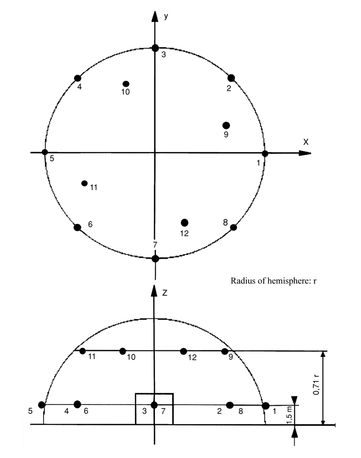
Additional microphone positions on the hemispherical measurement surface (EN ISO 3744:1995)
In addition to clauses 7.2.1 and 7.2.2 of EN ISO 3744:1995 a set of 12 microphones on the hemispherical measurement surface may be used. The location of 12 microphone positions distributed on the surface of a hemisphere of radius r are listed in the form of Cartesian coordinates in the following table. The radius r of the hemisphere shall be equal to or greater than twice the largest dimension of the reference parallelepiped. The reference parallelepiped is defined as the smallest possible rectangular parallelepiped just enclosing the equipment (without attachments) and terminating on the reflecting plane. The radius of the hemisphere shall be rounded to the nearest higher of the following values: 4, 10, 16 m.
The number (12) of microphones may be reduced to six, but the microphone positions 2, 4, 6, 8, 10 and 12 following the requirements of clause 7.4.2 of EN ISO 3744:1995 have to be used in any case.
Generally the arrangement with six microphone positions on a hemispherical measurement surface has to be used. If there are other specifications laid down in a noise test code in this Directive for a specific equipment, these specifications shall be used.
TABLE
Coordinates of the 12 microphone positions
| Number of microphone | x/r | y/r | z |
|---|---|---|---|
| 1 | 1 | 0 | 1,5 m |
| 2 | 0,7 | 0,7 | 1,5 m |
| 3 | 0 | 1 | 1,5 m |
| 4 | - 0,7 | 0,7 | 1,5 m |
| 5 | - 1 | 0 | 1,5 m |
| 6 | - 0,7 | - 0,7 | 1,5 m |
| 7 | 0 | - 1 | 1,5 m |
| 8 | 0,7 | - 0,7 | 1,5 m |
| 9 | 0,65 | 0,27 | 0,71 r |
| 10 | - 0,27 | 0,65 | 0,71 r |
| 11 | - 0,65 | - 0,27 | 0,71 r |
| 12 | 0,27 | - 0,65 | 0,71 r |
6.
Environmental correction K 2A
Equipment shall be measured on a reflecting surface of concrete or non-porous asphalt, then the environmental correction K 2A is set to K 2A = 0. If there are other specifications laid down in a noise test code of this Directive for a specific equipment, these specifications shall be used.
Figure
Additional microphone array on the hemisphere (12 microphone positions)
Annotations
Footnotes
- f1
-
Net power means the power in ‘EC kW’ obtained on the test bench at the end of the crankshaft, or its equivalent, measured in accordance with the EC method of measuring the power of internal combustion engines for road vehicles, except that the power of the engine cooling fan is excluded.