Appendix 12
United Kingdom
POSITIONING BASED ON GLOBAL NAVIGATION SATELLITE SYSTEM (GNSS)
1.
INTRODUCTION
This Appendix provides the technical requirements for the GNSS data used by the Vehicle Unit, including the protocols that must be implemented to assure the secure and correct data transfer of the positioning information.
The main articles in this Regulation (EU) No 165/2014 driving these requirements are: ‘Article 8 Recording of the position of the vehicle at certain points during the daily working period’, ‘Article 10 Interface with Intelligent Transport Systems’ and ‘Article 11 Detailed provisions for smart tachographs’.
1.1.
Scope
GNS_1
The Vehicle Unit shall collect location data from at least one GNSS to support the implementation of Article 8.
The Vehicle Unit may be with or without an external GNSS facility as described in Figure 1:
Figure 1
Different configurations for GNSS receiver

1.2.
Acronyms and notations
The following acronyms are used in this appendix:
Dilution of Precision
Elementary file GNSS Facility
European Geostationary Navigation Overlay Service
Global Navigation Satellite System
GPS DOP and active satellites
Horizontal Dilution of Precision
Interface Control Document
National Marine Electronics Association
Position Dilution of Precision
Recommended Minimum Specific
Signal in Space
Vertical Dilution of Precision
Vehicle Unit
2.
SPECIFICATION OF THE GNSS RECEIVER
Regardless of the configuration of the Smart Tachograph with or without an external GNSS facility, the provision of accurate and reliable positioning information is an essential element of the effective operation of the Smart Tachograph. Therefore, it is appropriate to require its compatibility with the services provided by the Galileo and European Geostationary Navigation Overlay Service (EGNOS) programmes as set out in Regulation (EU) No 1285/2013 of the European Parliament and of the Councilf1. The system established under the Galileo programme is an independent global satellite navigation system and the one established under the EGNOS programme is a regional satellite navigation system improving the quality of the Global Positioning System signal.
GNS_2
Manufacturers shall ensure that the GNSS receivers in the Smart Tachographs are compatible with the positioning services provided by the Galileo and the EGNOS systems. Manufacturers may also choose, in addition, compatibility with other satellite navigation systems.
GNS_3
The GNSS receiver shall have the capability to support Authentication on the Open Service of Galileo when such service will be provided by the Galileo system and supported by GNSS receiver manufacturers. However, for smart tachographs introduced in the market before the previous conditions are satisfied and not having the capability to support Authentication of the Open Service of Galileo, no retrofitting will be required.
3.
NMEA SENTENCES
This section describes the NMEA sentences used in the functioning of the Smart Tachograph. This section is valid both for the configuration of the Smart Tachograph with or without an external GNSS facility.
GNS_4
The location data is based on the NMEA sentence Recommended Minimum Specific (RMC) GNSS Data, which contains the Position information (Latitude, Longitude), Time in UTC format (hhmmss.ss), and Speed Over Ground in Knots plus additional values.
The format of the RMC sentence is the following (as from NMEA V4.1 standard):
Figure 2
Structure of the RMC sentence

The Status gives indication if the GNSS signal is available. Until the value of the Status is not set to A, the received data (e.g., on Time or Latitude/Longitude) cannot be used to record the position of the vehicle in the VU.
F1The resolution of the position is based on the format of the RMC sentence described above. The first part of the fields 3) and 5) are used to represent the degrees. The rest are used to represent the minutes with three decimals. So the resolution is 1/1000 of minute or 1/60000 of degree (because one minute is 1/60 of a degree).
GNS_5
The Vehicle Unit shall store in the VU database the position information for latitude and longitude with a resolution of 1/10 of minute or 1/600 of a degree as described in Appendix 1 for type GeoCoordinates.
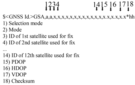
The GPS DOP and active satellites (GSA) command can be used by the VU to determine and record the signal availability and accuracy. In particular the HDOP is used to provide an indication on the level of accuracy of the recorded location data (see 4.2.2). The VU will store the value of the Horizontal Dilution of Precision (HDOP) calculated as the minimum of the HDOP values collected on the available GNSS systems.
The GNSS Id. indicates the corresponding NMEA Id. for every GNSS constellation and Satellite-Based Augmentation System (SBAS).
Figure 3
Structure of the GSA sentence
GNS_6
The GSA sentence shall be stored with record number ‘02’ to ‘06’.
GNS_7
The maximum size of the NMEA sentences (e.g., RMC, GSA or others), which can be used for the sizing of the read record command shall be 85 bytes (see Table 1).
4.
VEHICLE UNIT WITH AN EXTERNAL GNSS FACILITY
4.1.
Configuration
4.1.1
Main components and interfaces
In this configuration, the GNSS receiver is a part of the external GNSS facility.
GNS_8
The external GNSS facility must be powered with a specific vehicle interface.
GNS_9
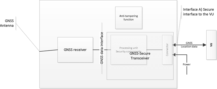
The external GNSS facility shall consist of the following components (see Figure 4):
- (a)
A commercial GNSS receiver to provide the position data through the GNSS data interface. For example, the GNSS data interface can be NMEA standard V4.10 where The GNSS receiver acts as a talker and transmit NMEA sentences to the GNSS Secure Transceiver with a frequency of 1Hz for the pre-defined set of NMEA sentences, which must include at least the RMC and GSA sentences. The implementation of the GNSS data interface is a choice of the manufacturers of the external GNSS facility.
- (b)
A transceiver unit (GNSS Secure Transceiver) with the capability to support standard ISO/IEC 7816-4:2013 (see 4.2.1) to communicate with the vehicle unit and support the GNSS data interface to the GNSS receiver. The unit is provided with a memory to store the identification data of the GNSS receiver and external GNSS facility.
- (c)
An enclosure system with tamper detection function, which encapsulate both the GNSS receiver and the GNSS Secure Transceiver. The tamper detection function shall implement the security protection measures as requested in the Protection Profile of the Smart Tachograph.
- (d)
A GNSS antenna installed on the vehicle and connected to the GNSS receiver through the enclosure system.
GNS_10
The external GNSS facility has at least the following external interfaces:
- (a)
the interface to the GNSS antenna installed on the vehicle truck, if an external antenna is used.
- (b)
the interface to the Vehicle Unit.
GNS_11
In the VU, the VU Secure Transceiver is the other end of the secure communication with the GNSS Secure Transceiver and it must support ISO/IEC 7816-4:2013 for the connection to the external GNSS facility.
GNS_12
For the physical layer of the communication with the external GNSS facility, the vehicule unit shall support ISO/IEC 7816-12:2005 or another standard able to support ISO/IEC 7816-4:2013. (see 4.2.1).
4.1.2
External GNSS facility state at the end of production
GNS_13
The external GNSS facility shall store the following values in the non-volatile memory of the GNSS Secure Transceiver when it leaves the factory:
the EGF_MA key pair and corresponding certificate,
the MSCA_VU-EGF certificate containing the MSCA_VU-EGF.PK public key to be used for verification of the EGF_MA certificate,
the EUR certificate containing the EUR.PK public key to be used for verification of the MSCA_VU-EGF certificate,
the EUR certificate whose validity period directly precedes the validity period of the EUR certificate to be used to verify the MSCA_VU-EGF certificate, if existing,
the link certificate linking these two EUR certificates, if existing,
the extended serial-number of the external GNSS facility,
operating system identifier of the GNSS facility,
type approval number of the external GNSS facility;
Identifier of the security component of the external GNSS module.
4.2.
Communication between the external GNSS facility and the vehicle unit
4.2.1
Communication Protocol
GNS_14
The communication protocol between the external GNSS facility and the vehicle unit shall support three functions:
- 1..
The collection and distribution of GNSS data (e.g., position, timing, speed),
- 2..
The collection of the configuration data of the external GNSS facility,
- 3..
The management protocol to support the coupling, mutual authentication and session key agreement between the external GNSS facility and the VU.
GNS_15
The communication protocol shall be based on standard ISO/IEC 7816-4:2013 with the VU Secure Transceiver playing the master role and the GNSS Secure Transceiver playing the slave role. The physical connection between the external GNSS facility and the vehicule unit is based on ISO/IEC 7816-12:2005 or another standard able to support ISO/IEC 7816-4:2013
GNS_16
In the communication protocol, extended length fields shall not be supported.
GNS_17
The communication protocol of ISO 7816 (both *-4:2013 and *-12:2005) between the external GNSS facility and the VU shall be set to T = 1.
GNS_18
Regarding the functions 1) the collection and distribution of GNSS data and 2) the collection of the configuration data of the external GNSS facility and 3) management protocol, the GNSS Secure Transceiver shall simulate a smart card with a file system architecture composed by a Master File (MF), a Dedicated File (DF) with Application Identifier specified in Appendix 1 chapter 6.2 (‘FF 44 54 45 47 4D’) and with 3 EFs containing certificates and one single Elementary File (EF.EGF) with file identifier equal to ‘2F2F’ as described in Table 1.
GNS_19
The GNSS Secure Transceiver shall store the data coming from the GNSS receiver and the configuration in the EF.EGF. This is a linear, variable-length record file with an identifier equal to ‘2F2F’ in hexadecimal format.
GNS_20
The GNSS Secure Transceiver shall use a memory to store the data and be able to perform at least 20 millions write/read cycles. Apart from this aspect, the internal design and implementation of the GNSS Secure Transceiver is left to the manufacturers.
The mapping of record numbers and data is provided in Table 1. Note that there are five GSA sentences for the GNSS constellations and Satellite-Based Augmentation System (SBAS).
GNS_21
The file structure is provided in Table 1. For the access conditions (ALW, NEV, SM-MAC) see Appendix 2 chapter 3.5.
| Table 1 | ||||
| File Structure | ||||
| Access conditions | ||||
|---|---|---|---|---|
| File | File ID | Read | Update | Encrypted |
| MF | 3F00 | |||
| EF.ICC | 0002 | ALW | NEV (by VU) | No |
| DF GNSS Facility | 0501 | ALW | NEV | No |
| EF EGF_MACertificate | C100 | ALW | NEV | No |
| EF CA_Certificate | C108 | ALW | NEV | No |
| EF Link_Certificate | C109 | ALW | NEV | No |
| EF.EGF | 2F2F | SM-MAC | NEV (by VU) | No |
| File / Data element | Record no | Size (bytes) | Default values | |
|---|---|---|---|---|
| Min | Max | |||
| MF | 552 | 1 031 | ||
| EF.ICC | ||||
| sensorGNSSSerialNumber | 8 | 8 | ||
| DF GNSS Facility | 612 | 1 023 | ||
| EF EGF_MACertificate | 204 | 341 | ||
| EGFCertificate | 204 | 341 | {00..00} | |
| EF CA_Certificate | 204 | 341 | ||
| MemberStateCertificate | 204 | 341 | {00..00} | |
| EF Link_Certificate | 204 | 341 | ||
| LinkCertificate | 204 | 341 | {00..00} | |
| EF.EGF | ||||
| RMC NMEA Sentence | ‘01’ | 85 | 85 | |
| 1st GSA NMEA Sentence | ‘02’ | 85 | 85 | |
| 2nd GSA NMEA Sentence | ‘03’ | 85 | 85 | |
| 3rd GSA NMEA Sentence | ‘04’ | 85 | 85 | |
| 4th GSA NMEA Sentence | ‘05’ | 85 | 85 | |
| 5th GSA NMEA Sentence | ‘06’ | 85 | 85 | |
| Extended serial-number of the external GNSS facility defined in Appendix 1 as SensorGNSSSerialNumber. | ‘07’ | 8 | 8 | |
| Operating system identifier of the GNSS Secure Transceiver defined in Appendix 1 as SensorOSIdentifier. | ‘08’ | 2 | 2 | |
| Type approval number of the external GNSS facility defined in Appendix 1 as SensorExternalGNSSApprovalNumber. | ‘09’ | 16 | 16 | |
| Identifier of the security component of the external GNSS facility defined in Appendix 1 as SensorExternalGNSSSCIdentifier | ‘10’ | 8 | 8 | |
| RFU — Reserved for Future Use | From ‘11’ to ‘FD’ | |||
4.2.2
Secure transfer of GNSS data
GNS_22
The secure transfer of GNSS position data shall be allowed only in the following conditions:
- 1..
The coupling process has been completed as described in Appendix 11. Common security mechanisms.
- 2..
The periodic mutual authentication and session key agreement between the VU and the external GNSS facility also described in Appendix 11. Common security mechanisms has been executed with the indicated frequency.
GNS_23
Every T seconds, where T is a value lower or equal to 10, unless coupling or mutual authentication and session key agreement takes place, the VU requests from the external GNSS facility the position information on the basis of the following flow:
- 1..
The VU requests location data from the External GNSS facility together with Dilution of Precision data (from the GSA NMEA sentence). The VU Secure Transceiver shall use the ISO/IEC 7816-4:2013 SELECT and READ RECORD(S) command in secure messaging authentication-only mode as described in Appendix 11 section 11.5 with the file identifier ‘2F2F’ and RECORD number equal to ‘01’ for RMC NMEA sentence and ‘02’,‘03’,‘04’,‘05’,‘06’ for GSA NMEA sentence.
- 2..
The last location data received is stored in the EF with identifier ‘2F2F’ and the records described in Table 1 in the GNSS secure transceiver as the GNSS secure transceiver receives NMEA data with a frequency of at least 1 Hz from the GNSS receiver through the GNSS data interface.
- 3..
The GNSS Secure Transceiver sends the response to the VU Secure Transceiver by using the APDU response message in secure messaging authentication-only mode as described in Appendix 11 section 11.5.
- 4..
The VU Secure Transceiver checks the authenticity and integrity of the received response. In case of positive outcome, the location data is transferred to the VU processor through the GNSS data interface.
- 5..
The VU processor checks the received data extracting the information (e.g., latitude, longitude, time) from the RMC NMEA sentence. The RMC NMEA sentence includes the information if the position is valid. If the position is not valid, the location data is not available yet and it cannot be used to record the position of the vehicle. If the position is valid, the VU processor also extracts the values of HDOP from GSA NMEA sentences and calculate the minimum value on the available satellite systems (i.e., when the fix is available).
- 6..
The VU processor stores the received and processed information such as latitude, longitude, time and speed in the VU in the format defined in Appendix 1 Data Dictionary as GeoCoordinates together with the value of HDOP calculated as the minimum of the HDOP values collected on the available GNSS systems.
4.2.3
Structure of the Read Record command
This section describes in detail the structure of the Read Record command. Secure messaging (authentication-only mode) is added as described in Appendix 11 Common security mechanisms.
GNS_24
The command shall support the Secure Messaging authentication-only-mode, see Appendix 11.
GNS_25
Command Message
| Byte | Length | Value | Description |
|---|---|---|---|
| CLA | 1 | ‘0Ch’ | Secure messaging asked. |
| INS | 1 | ‘B2h’ | Read Record |
| P1 | 1 | ‘XXh’ | Record number (‘00’ references the current record) |
| P2 | 1 | ‘04h’ | Read the record with the record number indicated in P1 |
| Le | 1 | ‘XXh’ | Length of data expected. Number of Bytes to be read. |
GNS_26
The record referenced in P1 becomes the current record.
| Byte | Length | Value | Description |
|---|---|---|---|
| #1-#X | X | ‘XX..XXh’ | Data read |
| SW | 2 | ‘XXXXh’ | Status Words (SW1,SW2) |
If the command is successful, the GNSS secure transceiver returns ‘9000’.
If the current file is not record oriented, the GNSS secure transceiver returns ‘6981’.
If the command is used with P1 = ‘00’ but there is no current EF the GNSS secure transceiver returns ‘6986’ (command not allowed).
If the record is not found, the GNSS secure transceiver returns ‘6A 83’.
If the external GNSS facility has detected tampering, it shall return status words ‘66 90’.
GNS_27
The GNSS Secure Transceiver shall support the following tachograph generation 2 commands specified in Appendix 2:
| Command | Reference |
|---|---|
| Select | Appendix 2 chapter 3.5.1 |
| Read Binary | Appendix 2 chapter 3.5.2 |
| Get Challenge | Appendix 2 chapter 3.5.4 |
| PSO: Verify Certificate | Appendix 2 chapter 3.5.7 |
| External Authenticate | Appendix 2 chapter 3.5.9 |
| General Authenticate | Appendix 2 chapter 3.5.10 |
| MSE:SET | Appendix 2 chapter 3.5.11 |
4.3.
Coupling, mutual authentication and session key agreement of the external GNSS facility with vehicle unit
The coupling, mutual authentication and session key agreement of the external GNSS facility with the vehicle unit is described in Appendix 11. Common security mechanisms, Chapter 11.
4.4.
Error Handling
This section describes how potential error conditions by the external GNSS facility are addressed and recorded in the VU.
4.4.1
Communication error with the external GNSS facility
GNS_28
If the VU does not manage to communicate to the coupled external GNSS facility for more than 20 continuous minutes, the VU shall generate and record in the VU an event of type EventFaultType with the value of enum ‘0E’H Communication error with the external GNSS facility and with the timestamp set to the current time. The event will be generated only if the following two conditions are satisfied: (a) the Smart Tachograph is not in calibration mode and (b) the vehicle is moving. In this context, a communication error is triggered when the VU Secure Transceiver does not receive a response message after a request message as described in 4.2.
4.4.2
Breach of the physical integrity of the external GNSS facility
GNS_29
If the external GNSS facility has been breached, the GNSS Secure Transceiver shall erase all its memory including cryptographic material. As described in GNS_25 and GNS_26, the VU shall detect tampering if the Response has status ‘6690’. The VU shall then generate an event of type EventFaultType enum ‘19’H Tamper detection of GNSS. Alternately, the external GNSS facility may not respond to any external request anymore.
4.4.3
Absence of position information from GNSS receiver
GNS_30
If the GNSS Secure Transceiver does not receive data from the GNSS receiver for more than 3 continuous hours, the GNSS Secure Transceiver shall generate a response message to the READ RECORD command with RECORD number equal to ‘01’ with a Data Field of 12 bytes all set to 0xFF. Upon reception of the Response message with this value of the data field, the VU shall generate and record an event of type EventFaultType enum ‘0D’H Absence of position information from GNSS receiver event with a timestamp equal to the current value of time only if the following two conditions are satisfied: a) the Smart Tachograph is not in calibration mode and b) the vehicle is moving.
4.4.4
External GNSS facility certificate expired
GNS_31
If the VU detects that the EGF certificate used for mutual authentication is not valid any longer, the VU shall generate and record a recording equipment event of type EventFaultType enum ‘ 1B ’ H External GNSS facility certificate expired with a timestamp equal to the current value of time. The VU shall still use the received GNSS position data.
Figure 4
Schema of the external GNSS facility
5.
VEHICLE UNIT WITHOUT AN EXTERNAL GNSS FACILITY
5.1.
Configuration
In this configuration, the GNSS receiver is inside the Vehicle Unit as described in Figure 1.
GNS_32
The GNSS receiver shall act as a talker and transmit NMEA sentences to the VU processor, which shall act as a listener with a frequency of 1/10 Hz or faster for the pre-defined set of NMEA sentences, which shall include at least the RMC and GSA sentences.
GNS_33
An external GNSS antenna installed on the vehicle or an internal GNSS antenna shall be connected to the VU.
5.2.
Error Handling
5.2.1
Absence of position information from GNSS receiver
GNS_34
If the VU does not receive data from the GNSS receiver for more than 3 continous hours, the VU shall generate and record an event of type EventFaultType enum ‘0D’H Absence of position information from GNSS receiver event with a timestamp equal to the current value of time only if the following two conditions are satisfied: (a) the Smart Tachograph is not in calibration mode and (b) the vehicle is moving.
6.
GNSS TIME CONFLICT
If the VU detects a discrepancy of more than 1 minute between the time of the vehicle unit's time measurement function and the time originating from the GNSS receiver, the VU will record an event of type EventFaultType enum ‘ 0B ’ H Time conflict (GNSS versus VU internal clock) . After a time conflict event has been triggered, the VU will not check the time discrepancy for the next 12 hours. This event shall not be triggered in cases no valid GNSS signal was detectable by the GNSS receiver within the last 30 days.
7.
VEHICLE MOTION CONFLICT
GNS_35
The VU shall trigger and record an Vehicle Motion Conflict event (see in requirement 84 in this Annex) with a timestamp equal to the current value of time, in case motion information calculated from the motion sensor is contradicted by motion information calculated from the internal GNSS receiver or from the external GNSS facility. For the purpose of detecting such contradictions, the median value of the speed differences between these sources shall be used, as specified below:
every 10 seconds maximum, the absolute value of the difference between the vehicle speed estimated from the GNSS and the one estimated from the motion sensor shall be computed.
all the computed values in a time window containing the last five minutes of movement shall be used to compute the median value.
the median value shall be computed as the average of 80 % of the remaining values, after having eliminated the highest ones in absolute values
The Vehicle Motion Conflict event shall be triggered if the median value is above 10 Km/h for five uninterrupted minutes of vehicle movement. Other independent sources of vehicle motion detection may optionnally be used, so that a more reliable detection of tachograph manipulations is provided. (Note: the use of the median on the last 5 minutes is applied to mitigate the risk of measurement outliers and transient values). This event shall not be triggered in the following conditions: (a) during a ferry/train crossing, (b) when the position information from the GNSS receiver shall not be available and (c) while in calibration mode.
Annotations
Textual amendments
Footnotes
- f1
-
Regulation (EU) No 1285/2013 of the European Parliament and of the Council of 11 December 2013 on the implementation and exploitation of European satellite navigation systems and repealing Council Regulation (EC) No 876/2002 and Regulation (EC) No 683/2008 of the European Parliament and of the Council (OJ L 347, 20.12.2013, p. 1).
Notes on Annex I C
Modifications
- C1
Annex 1C modified (21.8.2023) by The Drivers’ Hours and Tachographs (Amendment) Regulations 2023 (S.I. 2023/739), regs. 1(1), 3, Sch.