Paragraph 4 I1
England, Wales and Scotland
A Schedule 2 General Direction mentioned (by reference to paragraph number) in column 6 applies to the sign at the item number in question.
Sign table — Schedule 2, Part 6
(1) Item | (2) Description | (3) Diagram | (4) Variants | (5) Applicable provisions in Part 7 | (6) Schedule 2 General Directions |
|---|---|---|---|---|---|
| 1 | Diagram 501 Junction ahead controlled by a “GIVE WAY” or “STOP” sign, wherean indication may be given that the junction iswith a dual carriageway road | 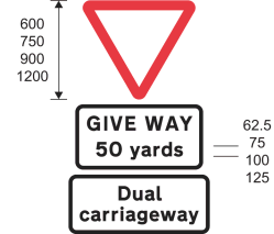 | 1. In the upper plate “GIVE WAY” is varied to “STOP” if the stop sign is placed at a junction ahead 2. The lower associated plate may be omitted 3. In the upper plate the distance may be varied | 6 | 4 |
| 2 | Diagram 560 Edge of carriageway or obstruction near that edge (Alternative types) |  | 1. The colour of the circular sign or the rectangular sign may be varied to white or amber 2. The surface of the rectangular sign may be curved | 4 | 5 |
| 3 | Diagram 515 Sharp deviation of route | 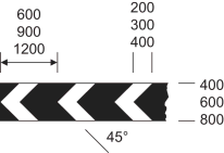 | 1. The chevrons may be reversed to point to the right 2. The number of chevrons may be varied 3. The corners of the sign may be rounded, with a radius not greater than 10 mm 4. The sign may be formed of a series of vertical flexible elements that need not have a horizontal cross section that is flat, provided that the elements extend to ground level to form the support for the sign and the support is coloured black 5. Where vertical flexible elements are used, the horizontal distance between the pointed ends of two consecutive chevrons may be increased by up to 4% of the dimensions shown in the diagram 6. Where vertical flexible elements are used, a yellow border may be added to the outside edge of the part of the sign that comprises the chevrons 7. Where vertical flexible elements are used, the sign may include a white arrow on a blue circular background as shown by the diagram in column 3 at item 1 of the sign table in Part 2 of Schedule 3. This is to be placed over the chevrons and any yellow border, and formed as part of those elements | 8, 9 | |
| 4 | Diagram 774 Location of a railway or tramway level crossing without gate or barrier |  | |||
| 5 | Diagram 781 Load gauge giving audible warning to drivers where vehicles exceed safe height under electrified overhead cables | 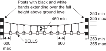 | 1. The number of bells may be increased or decreased according to the width of the road over which the sign is placed 2. The bells may be of any colour, provided each bell is of the same colour | 10 | |
| 6 | Diagrams 789, 789.1, 789.2 Countdown markers to railway or tramway level crossing |  | Each sign may be reversed |
Annotations
Commencement
- I1
Sch. 2 Pt. 6 para. 4 in force at 22.4.2016, see reg. 1(b)