Appendix 15
United Kingdom
Model information document relating to EU type-approval of a type of (or a type of a vehicle with regard to) a braking system
A.
GENERAL INFORMATION
2.
GENERAL INFORMATION CONCERNING SYSTEMS, COMPONENTS OR SEPARATE TECHNICAL UNITS
2.1.
Make(s) (trade name(s) of manufacturer): …
F12.2.
Type ( 6 ): …
2.2.1.
Commercial name(s) (if available): …
2.2.2.
Type-approval number(s) (49) (if available): …
2.2.3.
Type-approval(s) issued on (date, if available): …
2.2.4.
For components and separate technical units, location and method of attachment of the type-approval mark(s) (if available) (19): …
2.3.
Company name and address of manufacturer: …
2.3.1.
Name(s) and address(es) of assembly/manufacture plants: …
2.3.2.
Name and address of manufacturer's authorised representative (if any): …
2.4.
For systems and separate technical units, vehicle(s) for which they are intended for (21):
2.4.1.
Type (17): …
2.4.2.
Variant(s) (17): …
2.4.3.
Version(s) (17): …
2.4.4.
Commercial name(s) (if available): …
2.4.5.
Category, subcategory and speed index of the vehicle (2): …
3.
GENERAL CONSTRUCTION CHARACTERISTICS
3.1.
Photographs or drawings of a representative version of the vehicle: …
3.2.
Scale and dimensioned drawing of the whole vehicle: …
F23.3.
Axles and wheels:
3.3.1.
Number of axles and wheels: …
3.3.2.
Number and position of axles with twinned wheels (23): …
3.3.3.
Number and position of steered axles (23): …
3.3.4.
Number and position of powered axles (23): …
3.3.5.
Number and position of braked axles (23): …
3.4.
For C-category vehicles
3.4.1.
Crawler undercarriage configuration: set of track trains at front/set of track trains at rear/set of track trains at front and set of track trains at rear/continuous track train at each side of the vehicle (4)
3.4.2.
Number and position of powered set of track trains (22): …
3.4.3.
Number and position of braked set of track trains (22): …
3.4.4.
Steering for C-category vehicles
3.4.4.1.
Steering by changing the speed between the left-hand side and right-hand side track trains: yes/no/not applicable (4)
3.4.4.2.
Steering by pivoting of two opposite or all four track trains: yes/no/not applicable (4)
3.4.4.3.
Steering by articulation of the front and rear part of the vehicle around a central vertical axis: yes/no/not applicable (4)
3.4.4.4.
Steering by articulation of the front and rear part of the vehicle around a central vertical axis and by changing the direction of the wheels on the wheeled axle: yes/no/not applicable (4)
3.5.
Chassis
3.5.1.
Chassis overall drawing: …
3.5.2.
Type of chassis for categories T and C: backbone/central tube/ladder/articulated/chassis with side members/other (4) (if other: specify: …)
3.5.3.
Type of chassis for categories R and S: drawbar/rigid drawbar/centre-axle/other (4) (if other: specify: …)
3.12.
For R- and S-category vehicles, type of braking: unbraked/inertia-braked/continuous braked/semi-continuous braked/hydraulic braked/pneumatic braked (4)
4.
MASSES AND DIMENSIONS
(in kg and mm) (Refer to drawings where applicable)
4.1
Range of vehicle mass (overall)
4.1.1.
Unladen mass
4.1.1.1.
Unladen mass(es) in running order (13):
4.1.1.1.1.
Maximum: … kg (30)
4.1.1.1.2.
Minimum: … kg (30)
4.1.1.1.3.
Distribution of this (these) mass(es) among the axles: … kg
4.1.1.1.4.
In the case of a rigid drawbar or centre-axle R- or S-category vehicle indicate the vertical load on the coupling point (S): … kg
4.1.2.
Maximum mass(es), as declared by the manufacturer
4.1.2.1.
Technically permissible maximum laden mass(es) of the vehicle (13): … kg
4.1.2.1.1
Technically permissible maximum mass(es) per axle: Axle 1 … kg Axle 2 … kg Axle …: … kg
4.1.2.1.2.
In the case of a rigid drawbar or centre-axle R- or S-category vehicle indicate the vertical load on the front coupling point (S): … kg
4.1.2.1.3.
Limits on the distribution of this (these) mass(es) among the axles (specify the minimum limits in percentages on the front axle and on the rear axle): … %
F34.1.2.4.
. . . . . . . . . . . . . . . . . . . . . . . . . . . . . . . .
4.1.3.
Technically permissible towable mass(es) for T- or C-category vehicles for each chassis/ braking configuration of the R- or S-category vehicle (for R- and S-category vehicles, indicate the maximum permissible load(s) on the rear coupling point):
| Calculated using the partially laden condition defined by the tractor manufacturer in agreement with the technical service set out in point 3.1.1.2 of Annex II to Commission Delegated Regulation (EU) 2015/68. | |||
| R- and S category vehicle Brake | Drawbar | Rigid drawbar | Centre-axle |
|---|---|---|---|
| Unbraked f1 | … kg | … kg | … kg |
| Inertia-braked | … kg | … kg | … kg |
| Hydraulic braked | … kg | … kg | … kg |
| Pneumatic braked | … kg | … kg | … kg |
4.1.4.
Total technically permissible mass(es) of the tractor (T- or C-category vehicle) and towed vehicle (R- or S-category vehicle) combination for each chassis/braking configuration of the R- or S-category vehicle:
| R- and S category vehicle Brake | Drawbar | Rigid drawbar | Centre-axle |
|---|---|---|---|
| Unbraked | … kg | … kg | … kg |
| Inertia-braked | … kg | … kg | … kg |
| Hydraulic braked | … kg | … kg | … kg |
| Pneumatic braked | … kg | … kg | … kg |
4.1.5.
. . . . . . . . . . . . . . . . . . . . . . . . . . . . . . . .
4.2.
Range of vehicle dimensions (overall)
4.2.2.5.
Wheelbase (37): … mm
4.2.2.6.
Distance(s) between consecutive axles 1-2: … mm 2-3: … mm, 3-4: … mm, etc.
4.2.2.7.
For rigid draw bar and centre axle R- and S-category vehicles:
4.2.2.7.1.
Distance between the coupling point and the first axle: … mm
4.2.2.7.2.
Distance between the coupling point and the last axle: … mm
4.2.2.8.
Maximum and minimum width of track of each axle (measured between the symmetry planes of the single or twin tyres or of the tyres in triple formation normally fitted) (to be stated by the manufacturer) (38):
- 4.2.2.8.1.
Maximum: Axle 1 … mm Axle 2 … mm Axle …: … mm
- 4.2.2.8.2.
Minimum: Axle 1 … mm Axle 2 … mm Axle …: … mm
4.2.2.9.
Position of centre of gravity of the vehicle in the longitudinal, transverse and vertical direction: …
4.2.2.9.1.
For T2-, T4.1-, T4.3-categories and C2-, C4.1-, C4.3-categories, height of the centre of gravity, measured in relation to the ground using the tyres normally fitted on the vehicle: … mm
4.2.2.9.1.1.
For T2-and C2-categories, indicate the ratio between entry 4.2.2.9.1 and the average minimum track for each axle: Axle 1 … Axle 2 … Axle …: …
4.2.2.9.1.2.
For T4.1-and C4.1-categories, indicate the ratio between entry 4.2.2.9.1 and the average minimum track of all of the axles: …
5.
GENERAL POWERTRAIN CHARACTERISTICS
5.1.
Maximum vehicle speed
5.1.1.
Forward maximum vehicle speed
5.1.1.1.
Declared maximum design vehicle speed: … km/h
5.1.1.2.
Calculated maximum design vehicle speed in top gear (show factors used in calculation) (41): … km/h
5.1.1.3.
Measured maximum vehicle speed: … km/h (41)
5.1.2.
Rearward maximum vehicle speed (54)
5.1.2.1.
Declared rearward maximum design vehicle speed: … km/h
5.1.2.2.
. . . . . . . . . . . . . . . . . . . . . . . . . . . . . . . .
F45.2.
. . . . . . . . . . . . . . . . . . . . . . . . . . . . . . . .
5.3.
. . . . . . . . . . . . . . . . . . . . . . . . . . . . . . . .
5.4.
. . . . . . . . . . . . . . . . . . . . . . . . . . . . . . . .
B.
INFORMATION ON ENVIRONMENTAL AND PROPULSION PERFORMANCE
6.
ESSENTIAL CHARACTERISTICS OF THE ENGINE
6.1.7.
Category and sub-category of the engine ( 7 ): …
6.2.1.
Combustion Cycle: four stroke cycle/two stroke cycle/rotary/other (specify) ( 4 ): …
6.2.2.
Ignition Type: Compression ignition/spark ignition ( 4 )
6.2.3.1.
Cylinders' number: … and configuration ( 26 ):
6.3.2.1.
Declared rated speed: … rpm
6.3.2.1.2.
Declared rated net power: … kW
6.3.2.2.
Maximum power speed: … rpm
6.3.2.2.2.
Maximum net power: … kW
6.3.6.4.
Engine total swept volume: … cm 3
9.
ENERGY STORAGE DEVICE(S) ( 11 )
9.1.
Description: battery/capacitor/flywheel/generator ( 4 )
9.2.
Identification number: …
9.3.
Kind of electrochemical couple: …
9.4.
Energy stored
9.4.1.
For battery, voltage: … and capacity: … Ah in 2h
9.4.2.
For capacitor: … J
9.4.3.
For flywheel/generator(4): … J
9.4.3.1.
Flywheel moment of inertia: … kg m 2
9.4.3.1.1.
Additional moment of inertia if no gear is engaged: … kg m 2
9.5.
Charger: on-board/external/without ( 4 )
11.
DRIVE-TRAIN AND CONTROL ( 13 )
11.1.
Brief description and schematic drawing of the vehicle drive-train and its control system (transmission ratio change system, clutch control or any other element of drive-train): …
11.2.
Transmission
11.2.1.
Brief description and schematic drawing of transmission ratio change system(s) and its control: …
11.2.2.
Diagram and or drawing of the power transmission: …
11.2.3.
Type of power transmission: Gear (including planetary gear sets) / belt / hydrostatic / electric / other ( 4 ) (if other, specify: …)
11.2.4.
Brief description of the electrical/electronic components (if any): …
11.2.5.
Location relative to the engine: …
11.2.6.
Method of control: …
11.2.7.
Transfer box: with/without ( 4 )
11.2.8.
Type of transmission ratio change system: Mechanical (gear change) / Double clutch (gear change) / Semi-automatic (gear change) / Automatic (gear change) / Continuously Variable Transmission/ hydrostatic / not applicable / other ( 4 ) (if other, specify: …)
11.3.
Clutch (if any)
11.3.1.
Brief description and schematic drawing of the clutch and its control system:
11.3.2.
Maximum torque conversion: …
11.4.
Gear ratios
| Continuously variable transmission | |||||
| Gear | Internal gearbox ratios (ratios of engine to gearbox output shaft revolutions) | Internal transfer box ratios (ratios of engine to transfer box output shaft revolutions) | Final drive ratio(s) (ratio of gearbox output shaft to driven wheel revolutions) | Total gear ratios | Ratio (engine speed/vehicle speed) for manual transmission only |
|---|---|---|---|---|---|
| Maximum for CVT f2 1 2 3 | |||||
| Minimum for CVT Reverse 1 … | |||||
11.5.
Differential lock
11.5.1.
Differential lock: yes/no/optional ( 4 )
41.
SUSPENSION
41.1.
Brief description and schematic drawing of suspension and its control system for of each axle or group of axles or wheel: …
41.2.
Drawing of the suspension arrangements: …
41.3.
Level adjustment: yes/no/optional (4)
41.4.
Brief description of the electrical/electronic components: …
41.5.
Air-suspension for driving axle(s): yes/no (4)
41.5.1.
Suspension of driving axle(s) equivalent to air-suspension: yes/no (4)
41.5.2.
Frequency and damping of the oscillation of the sprung mass: …
41.6.
Air-suspension for non-driving axle(s): yes/no (4)
41.6.1.
Suspension of non-driving axle(s) equivalent to air-suspension: yes/no (4)
41.6.2.
Frequency and damping of the oscillation of the sprung mass: …
41.7.
Characteristics of the springing parts of the suspension (design, characteristics of the materials and dimensions): …
41.8.
Vehicle equipped with hydro-pneumatic/hydraulic/pneumatic (4) suspension
41.9.
Stabilisers: yes/no/optional (4)
41.10.
Shock absorbers: yes/no/optional (4)
41.11.
Other devices (if any): …
42.
AXLE(S) AND TYRES
42.1.
Description (including photographs and drawings) of the axle(s): …
42.2.
Material(s) and method of construction: …
42.3.
Make (where appropriate): …
42.4.
Type (where appropriate): …
42.5.
Maximum permissible mass supported by the axle(s): … kg
42.6.
Axle(s) dimensions:
- 42.6.1.
Length: … mm
- 42.6.2.
Width: … mm
42.7.
Braking connection to the axle(s): axial/radial/integrated/other (4) (if other, specify: …)
42.8.
Dimensions of the largest permissible tyres on braked axles: …
42.8.1.
Nominal rolling circumference of the largest tyres on braked axles: …
42.8.2.
Dimensions of the largest permissible tyres on powered axles: …
42.8.3.
Nominal rolling circumference of the of the largest tyres on powered axles: …
43.
BRAKING
43.1.
Brief description of the braking system(s) installed on the vehicle ( 55 ): …
43.2.
Specifications of the vehicle with respect to the control circuits of the pneumatic, hydraulic and/or electric control lines of the braking system(s) and a list of the supported messages and parameters: …
43.3.
. . . . . . . . . . . . . . . . . . . . . . . . . . . . . . . .
43.4.
Braking system(s)
43.4.1.
Description of the braking system(s) operation (including any electronic parts), electric block diagram, hydraulic or pneumatic circuit plan (55): …
43.4.2
Schematic drawing and operating sketch of the braking system(s) (55): …
43.4.3.
List of braking-system components, properly identified (55): …
43.4.4.
Technical explanation on the calculation for the braking system(s) (determination of the ratio of the total braking forces at the circumference of the wheels to the force applied to the braking control) (55): …
43.4.5.
External energy source(s) (if any) (characteristics, capacity of energy reservoirs, maximum and minimum pressure, pressure gauge and minimum-pressure warning device on the dashboard, vacuum reservoirs and supply valve, supply compressors, compliance with provisions regarding pressure equipment) (55): …
43.4.6.
Electronic braking system: yes/no/optional (4)
43.4.7.
Type-I test report number(s), in accordance with Annex VII to Commission Delegated Regulation (EU) 2015/68 (if applicable): …
43.5.
Braking transmission (on towing vehicle)
43.5.1.
Braking transmission of the service braking system on towing vehicle: mechanical/pneumatic/hydraulic/hydrostatic/without power assistance/power-assisted/fully powered transmission ( 4 )
43.5.2.
Transmission technology: pneumatic/hydraulic/both pneumatic and hydraulic (4)
43.5.3.
Locking of left and right braking controls: yes/no ( 4 )
43.6.
Towed vehicle braking control devices (on towing vehicle)
43.6.1.
Towed vehicle braking control system technology: Hydraulic / Pneumatic / Electric/None ( 4 )
43.6.2.
Description of the connectors, couplings and safety devices (including drawings, sketches and the identification of any electronic parts): …
43.6.2.1.
Pneumatic connection type: Two lines/None ( 4 )
43.6.2.1.1.
Pneumatic supply pressure (two lines): … kPa
43.6.2.1.2.
Electrical control line: yes/no ( 4 )
43.6.2.2.
Hydraulic connection type: Single line / Two lines / None ( 4 )
43.6.2.2.1.
Hydraulic supply pressure: Single line: … kPa Two lines: … kPa
43.6.2.2.2.
Presence of ISO 7638:2003 connector ( 15 ): yes/no ( 4 )
43.7.
Towed vehicle braking devices (on towed vehicle)
43.7.1.
Towed vehicle braking control system technology: Hydraulic / Pneumatic / Electric/ Inertia / None ( 4 )
43.7.2.
Towed vehicle-brake actuating device: Drum / Disc / Other ( 4 )
43.7.2.1.
Description and characteristics: …
43.7.3.
Description of the connectors, couplings and safety devices (including drawings, sketches and the identification of any electronic parts): …
43.7.3.1.
Pneumatic connection type: Two lines/None ( 4 )
43.7.3.1.1.
Electrical control line: yes/no ( 4 )
43.7.3.2.
Hydraulic connection type: Two lines / None ( 4 )
43.7.3.2.1.
Presence of ISO 7638:2003 connector ( 15 ): yes/no ( 4 )
F543.A
TOWED VEHICLE AXLE AND BRAKE INFORMATION DOCUMENT WITH RESPECT TO THE ALTERNATIVE TYPE I AND TYPE III PROCEDURE
43.A.1.
General
43.A.1.1.
Name and address of axle or vehicle manufacturer:
43.A.2.
Axle data
43.A.2.1.
Manufacturer (name and address): …
43.A.2.2.
Type/variant: …
43.A.2.3.
Axle identifier: ID1- …
43.A.2.4.
Test axle load (Fe): … daN
43.A.2.5.
Wheel and brake data according to the following figures 1A and 1B
43.A.3.
Brake
43.A.3.1.
General information
43.A.3.1.1.
Make:
43.A.3.1.2.
Manufacturer (name and address):
43.A.3.1.3.
Type of brake (e.g. drum / disc):
43.A.3.1.3.1.
Variant (e.g. S-cam, single wedge etc.):
43.A.3.1.4.
Brake identifier: ID2-
43.A.3.1.5.
Brake data according to the figures 2A and 2B:
43.A.3.2.
Drum brake data
43.A.3.2.1.
Brake adjustment device (external/integrated): …
43.A.3.2.2.
Declared maximum brake input torque C max : … Nm
43.A.3.2.3.
Mechanical efficiency: η =…
43.A.3.2.4.
Declared brake input threshold torque C 0,dec : … Nm
43.A.3.2.5.
Effective length of the cam shaft: … mm
43.A.3.3.
Brake drum
43.A.3.3.1.
Max diameter of friction surface (wear limit) … mm
43.A.3.3.2.
Base material: …
43.A.3.3.3.
Declared mass: … kg
43.A.3.3.4.
Nominal mass: … kg
43.A.3.4.
Brake lining
43.A.3.4.1.
Manufacturer and address …
43.A.3.4.2.
Make …
43.A.3.4.3.
Type …
43.A.3.4.4.
Identification (type identification on lining) …
43.A.3.4.5.
Minimum thickness (wear limit) … mm
43.A.3.4.6.
Method of attaching friction material to brake shoe: …
43.A.3.4.6.1.
… Worst case of attachment (in the case of more than one):
43.A.3.5.
Disc brake data
43.A.3.5.1.
Connection type to the axle (axial, radial, integrated, etc.): …
43.A.3.5.2.
Brake adjustment device (external/integrated): …
43.A.3.5.3.
Max. actuation stroke: … mm
43.A.3.5.4.
Declared maximum input force Th Amax : … daN
43.A.3.5.4.1
Cmax = Th Amax · l e : … Nm
43.A.3.5.5.
Friction radius: r e = … mm
43.A.3.5.6.
Lever length: l e = … mm
43.A.3.5.7.
Input/output ratio (l e /e e ): i = …
43.A.3.5.8.
Mechanical efficiency: η = …
43.A.3.5.9.
Declared brake input threshold force Th A0,dec : … N
43.A.3.5.9.1.
C 0,dec = Th A0,dec · l e : … Nm
43.A.3.5.10.
Minimum rotor thickness (wear limit): … mm
43.A.3.6.
Brake disc data …
43.A.3.6.1.
Disc type description: …
43.A.3.6.2.
Connection/mounting to the hub: …
43.A.3.6.3.
Ventilation (yes/no): …
43.A.3.6.4.
Declared mass: … kg
43.A.3.6.5.
Nominal mass: … kg
43.A.3.6.6.
Declared external diameter: … mm
43.A.3.6.7.
Minimum external diameter: … mm
43.A.3.6.8.
Inner diameter of friction ring: … mm
43.A.3.6.9.
Width of ventilation channel (if appl.): … mm
43.A.3.6.10.
Base material: …
43.A.3.7.
Brake pad data …
43.A.3.7.1.
Manufacturer and address: …
43.A.3.7.2.
Make:
43.A.3.7.3.
Type: …
43.A.3.7.4.
Identification (type identification on pad back plate): …
43.A.3.7.5.
Minimum thickness (wear limit): … mm
43.A.3.7.6.
Method of attaching friction material to pad back plate: …
43.A.3.7.6.1.
Worst case of attachment (in the case of more than one): …
Figure 1A

Figure 1B

Figure 2A

Figure 2B
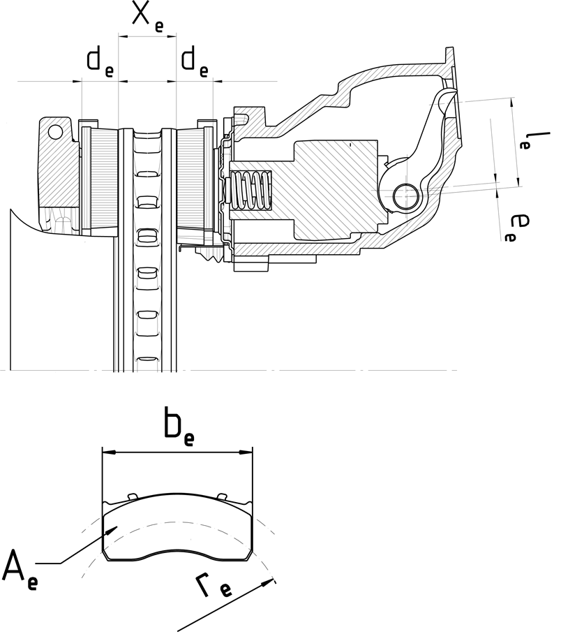
| xe (mm) | ae (mm) | he (mm) | ce (mm) | de (mm) | ee (mm) | α0e | α1e | be (mm) | re (mm) | Ae (cm2) | S1e (mm) | S2e (mm) | S3e (mm) |
|---|---|---|---|---|---|---|---|---|---|---|---|---|---|
Annotations
Textual amendments
- F1
- F2
- F3
- F4
- F5
Footnotes
- f1
-
Calculated using the partially laden condition defined by the tractor manufacturer in agreement with the technical service set out in point 3.1.1.2 of Annex II to Commission Delegated Regulation (EU) 2015/68.
- f2
-
Continuously variable transmission